Improved Casing Installation Using Expendable Downhole Vibratory Tools
6/15/2015
Roger L. Schultz, Thru Tubing Solutions/TTS Drilling Solutions
Excerpt from Oilfield Technology, May 2014, "Improving Installation"
Problems with Casing Installation in Horizontal Wells
Horizontal well construction continues to dominate the landscape. The horizontal sections of these wells have continued to get longer and longer as equipment and methods used in constructing these wells have improved. As lateral lengths have increased, so have the challenges associated with running casing and achieving good cement integrity. The primary issue seen while running casing is the high friction associated with horizontal well profiles and the absence of adequate vertical pipe weight to help overcome frictional forces. The high friction often requires the operator to apply excessive torque and force to the casing string and other completion components. Damage to casing and completion equipment such as frac sleeves and swellable packers commonly occurs.
A second issue which often occurs in horizontal wells is lack of cement integrity. Channeling of cement and poor cement/casing bond is common in both the horizontal portion of the intermediate casing in the curve and in the lateral liner/casing.
Operators are increasingly running downhole vibratory tools to reduce damage to casing/completion hardware and to improve cement integrity. Vibratory tools help to overcome friction greatly reducing the torque and force required to install casing therefore minimzing potential damage to casing, frac sleeves, packers, etc. Cement integrity is improved by the casing vibration produced when cement is pumped through the vibratory tool. Drillable tools are available so they can be run anywhere in the casing string. These tools are typically one-use, expendable tools which are included in the casing string and are either drilled out, or remain in the well with the casing string.
There are now many configurations available for using vibratory tools during casing installation. These include tools run at the end of casing, multiple drillable tools run at various positions within the casing string, landable tools which can be run into casing from the surface, as well as other configurations. In this writing an overview of the operating methodology and effectiveness of these tools will be discussed. Case study information showing the effectiveness of this technology will be presented.
Casing Friction Issues
The ratio of lateral length to vertical well depth has continually increased. The lack of vertical well depth compared to horizontal depth means that there is a reduced amount of weight available to push the casing out into the horizontal section as compared to the length of pipe creating frictional contact with the wellbore. Additionally, the casing friction in the horizontal section is higher than in a typical vertical section because the casing string, as well as friction causing debris is lying on the bottom of the hole due to gravity. The casing string is relatively stiff and has low clearance within the wellbore. This situation causes any deviation in the wellbore to create additional friction due to forced contact between the casing string and the borehole. Once the friction gets high enough to impede the advancement of casing into the well, rough handling of the casing is often necessary to get the casing to bottom. In these situations casing is often handled very roughly. It is not uncommon for casing to be “hammered” into the well using the blocks on the rig. Rotating the casing helps to break the static friction which aids in getting the casing to move. Rotation sometimes results in over-torqued casing. Over-torqueing connections causes rolling of the pin threads into the ID causing an effectively reduced ID and high wear and friction when workstrings are later run into the cased wellbore. When sleeve systems are deployed in the casing string, these components can easily be damaged, or sleeves prematurely shifted while being run into the well on casing string which is handled with excessive roughness. Often the casing is left in an extremely high stress state which causes issues later on in the life of the well.
High friction also greatly slows the speed with which casing can be run having a direct impact on operational costs.
The problems caused by excessive friction in horizontal wells include:
• Failure to get casing to bottom.
• Excessive time spent running casing.
• High residual stress left in casing and other downhole components
• Damage to casing due to rough handling during trip in.
• Over-torqued connections during rotation to get casing in hole.
• Damaged sleeve systems due to rough handling.
How Do Downhole Vibratory Casing Tools Work?
Reliable expendable vibratory casing tool technology has recently become available. This tool is a “flow-interrupting tool which modulates the flow of fluid through the tool. This type of tool utilizes a “valve” function in which the flow restriction through the tool varies with time. This periodic change in flow restriction causes oscillating backpressure across the tool as fluid is pumped through it. As a column of fluid travels through the workstring it encounters this changing flow restriction. When the flow is interrupted by the vibratory tool the pressure above the tool increases due to both the water hammer effect as the fluid column decelerates and the continued flow of fluid into the workstring by the positive displacement surface pumps. This increased pressure acts across the hydraulic area of the workstring causing the workstring to elongate causing downward movement of the workstring at the tool. When the flow restriction across the tool then decreases, fluid pressure above the tool is relieved and the workstring contracts to its original length. This process repeats itself over and over as fluid flows through the tool causing vibration of the workstring.
Additionally, as the tool modulates the flow through it, fluid pulsation is created at the exit of the tool. These means that as mud or cement is pumped through the tool, there is pulsating flow exiting and flowing around the casing shoe. This fluid pulsation tends to break fluid channeling and create uniform flow up the outside of the casing. The vibration of the casing string and fluid pulsation during cementing operations helps to ensure a high quality cement job by reducing voids and channeling much like vibratory tools used in the construction industry which ensure high quality concrete with no holes or voids. Vibratory tool for casing can be made drillable, so they are much like any other piece of floating equipment in terms of flexibility of future well operations.
The operation of a flow interrupting vibratory casing tool is depicted in figure 1.
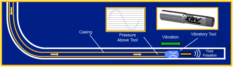 Figure 1. Operation of a Flow Interrupting Vibratory Casing Tool.
Fluidic Flow-Modulating Vibratory Casing Tool
This is a relatively new type of flow interrupting vibratory tool technology which has been used extensively in coiled tubing and drilling operations and more recently in casing installation applications. The tool utilizes a specialized flow path to create a varying flow resistance which acts much like an opening and closing valve without having any moving parts or elastomeric components. The “valve” function is created using fluidic elements coupled together to create a self-induced, oscillating change in pressure above the tool.
Characteristics of Fluidic Flow Modulating tool
• No moving parts…..highly reliable
• No elastomers….no issues with fluids, chemicals or gases.
• No temperature limitation
• Very short and rugged
• Drillable
This technology is uniquely suited for the casing application. The simple, no moving parts design makes it possible to make a tool which is very effective, but inexpensive enough to manufacture that it can be used as an expendable tool that is left in the well.
Test Data for Casing Vibratory Tool
Figure 2 shows a field test setup in which casing XRV data was recorded. An XRV tool was suspended from a drilling rig and the rig pumps were used to circulate fluid through the tool. The internal components of the tool tested are typical for 4.5” and 5.5” casing tools. A high-speed data acquisition system was used to record the resulting pressure drop across the tool. Figure 3 shows the recorded data. This data shows a 300-400 psi peak-to-peak oscillating pressure change across the tool at a 160 gpm flow rate.
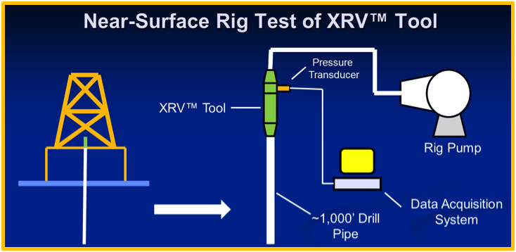
Figure 2. Test Configuration for Vibratory Casing Tool
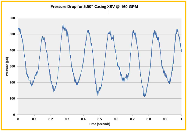 Figure 3. Pressure Drop for 5.5” Vibratory Casing Tool Rig Test.
If the flowrate through the vibratory tool is increased, the peak-to-peak pressure drop across the tool also increases. The vibratory load generated during the operation of a casing XRV tool can be computed by multiplying the peak-to-peak pressure drop shown in figure 3 by the hydraulic cross-section (internal area) of the casing string. Figure 4 shows the resulting vibratory load for various pump rates as a function of casing ID.
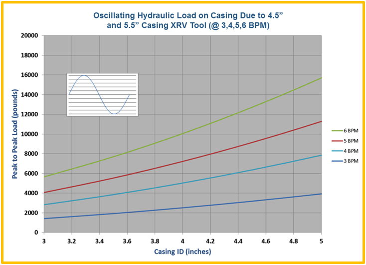
Figure 4. Vibratory Load Produced by XRVTM Casing Vibratory Tool at Various Flow Rates.
It can be seen by examining figure 4 that the vibratory force imparted to the casing can be very high if desired, even with a moderately low average pressure drop across the vibratory tools. In other words, very significant vibratory forces can be imparted to the casing string with only a small increase in circulating pressure.
Case Studies Involving Vibratory Casing Tools
The following case studies show how vibratory casing tools can be beneficial.
Case Study #1
Details:
Formation: Woodford Shale
Location: Central Oklahoma
Tools Used: 5.5” Casing XRV™
Fluid: 9.25 ppg Water Based w/ 56 Viscosity
Pump Rate: 250 - 420 gpm ( 0.9 - 1.6 m3/min)
Drill Pipe: 5.5” Casing
Lateral Length: 5500’ (1676m)
Total Depth: 11,550’ (3520m)
Days In Use: 2 Days
Results:
The customer wanted to compare the casing installation of two wells, spaced one mile apart; particularly focusing on the overall time taken to run the casing in hole as well as any difficulties or force needed to push the casing to bottom. A vibratory casing tool was used on the first well where the casing was installed to TD and the cement job was completed in a total of 36 hours. The casing installation and cementing of the second well, without using vibratory casing tool took a total of 54 hours to complete. It took 33% less time to run the casing on the job where the vibratory casing tool was used.
Case Study #2
Details:
Formation: Niobrara Shale
Location: Wyoming
Tools Used: 5.5” Casing XRV™
Fluid: 9.1 ppg Water Based w/ 56 Viscosity
Pump Rate: 250 - 325 gpm ( 0.9 - 1.23 m3/min)
Drill Pipe: 5.5” Casing
Lateral Length: 6000’ (1829m)
Total Depth: 12,333’ (3759m)
Days In Use: 1 Day
Results:
A customer in the Niobrara Shale formation continuously had problems running casing to bottom; a previous well had taken upwards of 17 hours for the final 3000’ (914m) to reach bottom. The customer was looking for a viable solution to decrease run time and minimize force needed to install casing. After implementing a vibratory casing tool, the customer was able to successfully run 12,333’ (3759m) of casing to bottom in a total of 12 hours without any issues.
Case Study #3
Details:
Location: Hinton, Alberta
Tools Used: 4.5” Casing XRV™
Pump Rate: 80-200 gpm ( 0.3 – 0.75 m3/min)
Casing: 4.5” Casing
Lateral Length: 4855’ (1480m)
Total Depth: 9,973 (3040m)
Days In Use: 1 Day
Results:
A customer was attempting to run a frac sleeve system which got stuck on a severe dog leg in the well. When the string was pulled out of the hole it was discovered that a frac sleeve sheath had sheared off in the wellbore. With the obstruction in the well, many remedial options were discussed all with the worst case scenario as getting hung-up at the same point. Management decided to move forward with the open-hole packer assembly to mitigate extra costs associated with reaming runs and side-track and cemented/plug & perf options. The customer researched options to improve chances of getting past the obstruction without adding risk or excessive costs to the operation. A vibratory casing tool was selected as a minimal risk solution. The operation was successful and the vibratory tool allowed the tool assembly to pass the obstruction and reach bottom.
Conclusion
In order to combat the negative effects of friction, the industry has embraced downhole vibratory tool technologies. New drillable, low-cost, expendable vibratory casing tools are now being used to resolve friction related issues that operators often experience when running casing, frac sleeves and swellable packers.
This technology allows casing strings, sleeves, swell packers etc. to be run faster, with minimal force and torque required, greatly reducing the risk of damage while reducing installation cost by saving time. Additionally, the vibrating action produced by these tools during the cement job helps to improve cement bond and integrity.
